8400K Digital Optical Micrometer
Article No. 12166
8400K Digital Optical Micrometer
- 8400K Optical Depth Micrometer Kit


Features
- Hand-held microscope and optical depth gauge
- Uses a manual focus method to measure surface indentations and protrusions
- Primarily used for measuring damage on critical aircraft surfaces to determine severity, repairability, and airworthiness
- For use on flat and curved surfaces
- Inspect metals, natural and synthetic polymers, composites, painted or chemically treated finishes, fibers, and transparent materials
- The Digital Depth Optical Micrometer measures:
- Scratches, corrosion pits, dings, impact dents, and other surface damage
- The depth of engraving, etching and other part markings
- Transparencies for overall thickness, and the depth and thickness of crazing and fractures, and imbedded bubbles or seeds
- The height of burrs, chips and small surface protrusions
- Can verify dimensions for compliance to drawings or other specifications
- Comes with ISO Calibration Certificate
- It also includes 3 interchangeable bases, 2 black and 1 clear
- A 3-Leg tripod base used for most flat and simple curved surfaces.
- A 4-Leg base used on broad convex and concave surfaces.
- A new and improved acrylic V-block base for leading edges, small diameters, outside angles, and flat surfaces next to an edge.
- The Optical Micrometer can easily be connected to a laptop or tablet by swapping the eyepiece with a microscope camera. Annotations of the depth and other notes can easily be made to the images to produce detailed inspection reports. The image quality is excellent; the camera captures every detail and records exactly what would be seen by looking through the eyepiece (Included in 15500 kit only).
Technical Attributes
-
- Data
-
Part No.: 12166 15458 15500 Description: 8400K 8400K Certified Kit 8400K All-in-One Kit Dimensions: 14" x 12" x 6" 14" x 12" x 6" 22" x 18" x 12" Kit Weight: 7 lbs 7 lbs 32 lbs Micrometer Size: 9"H x 3" Diameter Base, 1.5 lbs Magnification Accuracy Max Depth Field of View 40X ±0.001" 1.150" 0.18" Diameter 80X ±0.001" 1.150" 0.10" Diameter 100X ±0.001" 0.250" 0.07" Diameter 200X ±0.001" 0.250" 0.04" Diameter Diameter Field of View: 10X objective (with 20X / 10X eyepieces): .040" / .070" wide
4X objective (with 20X / 10X eyepieces): .110" / .175" wideApproximate Magnification Power: 40X & 80X (with 4X objective) 100X, 200X (with 10X objective) Use 10X reticule eyepiece with the 10X objective lens only. Scale range of eyepiece is .040 inches with .002" accuracy and .001" resolution (also 1.00mm, with .02mm accuracy and .01mm resolution).
The working distance for the 10X lens is .250", for 4x lens, 1.275" above surface. The "working distance" refers to how far the objective lens is from a surface when in focus. This means that .250" and 1.275" are the maximum scratch depths that could be observed, in theory, without the lens "bumping into" the surface. The 4X objective provides the most clearance, and is thus used for larger features and for transparencies, where the near and far sides can be focused upon without lens interference.
The 4X objective lens is ideal for transparencies. The wide field of view allows observation of more and larger features, and the long working distance prevents the lens from contacting surface - even when focusing on the far side of a thick transparency (up to 1.9"). Accuracy is not compromised by using the 4X objective.
More Information
Reliable Measurements
Traditional depth gauges depend on a probe making physical contact with the lowest point of the damage. If geometry prevents the probe from reaching the bottom, the resulting measurement will be false. This leads to improper (and potentially unsafe) damage assessments.
Repeatable Inspections
Depth gauges are difficult to hold still, especially at an angle. When compared to the Optical Micrometer, repeatability is poor on anything other than a flat surface.
Reduced Risk
Seeing the damage can expose a more serious problem, like exposed substrate material or a structural crack.
Quick and Clear Results
A vernier scale is hard to read and requires manual depth calculations. The zero feature and digital display eliminate human errors due to misreading the scale and incorrect math.
Leading Edges
A leading edge is the front section of a wing, propeller, turbine blade, stabilizer, or other airfoil. During a flight, the leading edge is repeatedly hit by debris like sand, pebbles, ice, insects and even birds. This always results in strike damage and erosion over time. The curved shape of a leading edge makes taking measurements with a pit depth gauge almost impossible. The V-Block Base holds the Optical Micrometer steady on a curve, so it is ideal for measurements on a leading edge. It can measure the depth of a pit in seconds, versus the pit depth gauge that can’t produce a result at all, or worse gives a faulty one. Especially when the type of damage is so common, it is an expensive problem when maintainers don’t have an inspection method that’s fast, reliable and repeatable.
Blending, Blasting and Polishing
In most cases, minor surface damage doesn’t impact the performance or safety of an aircraft and may be repaired. The most common method is smoothing out the harsh edges of a damaged area to remove the stress concentration and prevent further corrosion or cracking. Blending, blasting, polishing, and peening differ in application, but are similar in that they all remove material and leave a recessed area in the surface. This means that the overall thickness of the surface is reduced by (at least) the depth of the original damage. If a scratch is deep enough to cause the overall thickness to exceed limits, it will still be beyond limits after the repair. There’s no point wasting time on damage that’s beyond limits. If a part needs replacing, it’s best to know right away to reduce down-time.
Transparent Surfaces
Windshields, windows and canopies are subject to extreme conditions from atmospheric pressure, changes in temperature, UV radiation, erosion and other impact damage. Left unrepaired, seemingly small problems like crazing and scratches can quickly lead to an expensive replacement or, much worse, failure.
Surface Damage: Chips, Crazing, Scratches, Scribes, and Strikes
The method for measuring the depth of surface damage on a transparency is the same as any other surface. Focus on the surface next to the damage, zero the display, and focus down into the bottom.
Overall Thickness
Measuring overall thickness is the same except that, instead the bottom of a scratch, the second surface is the far side of the glass. Transparencies usually have extremely shallow surface marks, like polishing lines and microscratches, that allows for easy focus on either surface. If it difficult to locate either side use 2 different colored markers, like Sharpies or highlighters, to make a line on each side of the transparency. The lines should cross to create a target to position in the center of the field of view.
**Very Important** When measuring overall thickness (only), the result initially displayed is not accurate. To calculate the overall thickness, multiply the initial result by the refraction index. A normal refraction index for transparent materials is approximately 1.5:
- PMMA (acrylic, Lucite) 1.49
- Plate/Window Glass 1.52
- Polycarbonate (Lexan) 1.58
- Tables of refraction indexes of other materials are readily available online.
Note: Surface and embedded damage are air space and therefore are not subject to the refraction index.
Procedure
Basic Principle
The Micrometer uses focus to measure the distance between two points on different surfaces (at different heights). Features at the same depth will appear in focus and features above or below will be blurry. Turning the Focus Adjust moves the focus up and down.
Procedure
- Fine position the Micrometer so the edge of the recessed area, like a scratch, is in the center of the field of view.
- Focus on the top surface directly next to the scratch
- When the surface area is in sharpest focus, press the ZERO/ABS button on the Digital Display to set a starting point for the measurement.
- Without moving the Micrometer, focus down to the bottom of the damage. To find the true lowest point, focus down passed what seems to be the last area in focus until nothing else appears in focus below, then come back up to the first area that comes into sharp focus.
- Record the measurement from the Digital Display.
- Verify the measurement by refocusing up to the top surface. The Digital Display should show "0.0000“ again.
The entire measurement cycle should be completed by the same person. When switching users, always reset zero or the result may be inaccurate. The Micrometer does not have prismatic correction, the view through the eyepiece is inverted.
Calibration Procedure - Recommended Yearly
Equipment needed: 4x Rectangular Gauge Block (0.005”-0.200”), Grade 0, ASME B89.1.9, calibrated and traceable to NIST. Recommend Sizes: 0.005”, 0.015”, 0.0625”, 0.100”
- Wring 0.005” and 0.100” gage blocks by sliding one block perpendicularly across the top of the other, then rotate lengthwise and slide to create a step with the 0.100” gage block on the bottom.
- Place micrometer over the step and position so approximately one-half of the field of view is on the upper block.
- Focus on the top surface of the upper block. Zero “0.0000” digital display.
- Focus on lower block. Read display; if equipment is functioning properly the display will show the exact thickness of upper block.
- Repeat steps 1-5, using the 0.015” and 0.0625” as the upper block.
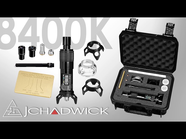
Delivery Content
- Optical Micrometer with Digital display
- 3 Interchangeable bases
- 2 eyepieces & 2 objective lenses
- Flashlight w/ spare batteries
- Sealed foam-lined case
- Scratch sample plate (for demonstration & training, not for calibration)
- Certificate of Conformance (COC)
Downloads
Accessories