Universal Blade Film Applicator
Article No. 10699
Univ Blade Applicator 0-50 2" Path
- Universal Blade Applicator
- Range: 0-50 mil clearance
- 2" path


Features
The Universal Blade Film Applicator provides one of the most accurate and the most reproducible method of applying a coating to a flat surface for further evaluation. Since most physical properties are dependent on applied thickness, it is of paramount importance that not only must thickness of a coating be reproducible, but also the correct value of thickness must be known. Applicator blades having the most common contour will, on the average, apply a wet coating thickness which is just one half of the physical clearance between the blade and the surface receiving the coating. There is some variation in this ratio depending on the physical properties of the coating and the rate of "draw down" of the coating on the surface by the applicator. The careful operator will determine this ratio for his particular material and conditions of operation.
- Unique blade applicator of simple and sturdy design
- Applications: Uniform Film Thickness - Continuously variable from 0 to 5 and 0 to 25 mils, Films of Wedge Shape - Any gradient between 0 to 5 and 0 to 25 mils¹, Hiding Power, Spreading Rate, Fineness of Grind (¹Applied wet film thickness is normally one-half of gate clearance.)
- Machined from the finest quality aluminum alloy
- It is ruggedly designed and constructed and with reasonable care and cleaning following each use will provide years of satisfactory service.
- The blade of the Universal Blade Applicator is produced in 2, 4, 6, 8, 10 and 12 inch standard lengths.
- All blades are identical except for their length.
- They are two inches high, one inch wide and with a lower surface contour which is symmetrical, and similar to "bird" type blades, permitting the assembly to be operated in either direction.
- Two different applicator ranges are available
- 0 to 50 mil clearance
- 0 to 10 mil clearance
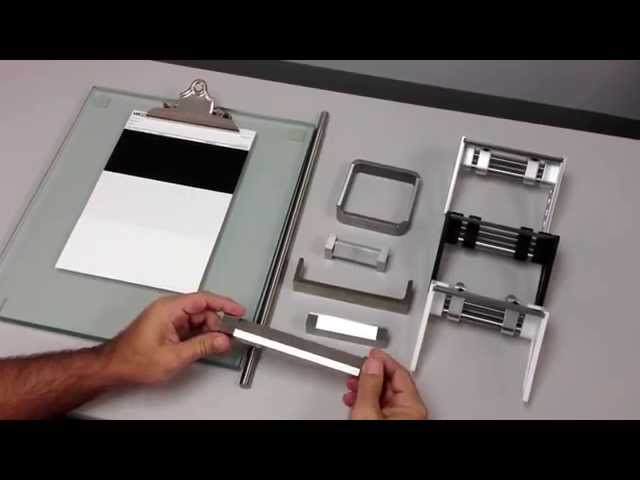
- Consists of a blade and two side support plates. Each side plate is clamped to the blade by a knurled head bolt. Vertical clearance of the blade with respect to the lower edges of the supporting side plates is controlled by blade members that extend over the side plates.
- The side plates, which determine the range, are identical except for the gradient of the height increase from the front to the rear of the sideplate and are four inches long and abut 1-3/4 inches high. The side plates and the blade are produced as a matched assembly. Make sure the reference marks on the plates and the blade match in any reassembly. Do not interchange parts between different applicators.
- For greatest accuracy only the inside edges of the side plates come into contact with the surface to receive the test material. The side plates are higher in the back than at the front. Therefore as the sideplate is moved forward the clearance of the blade increases on the scale.
- Has Wedge Expansion Feature. The sideplate lower surface is designed so that only the inside edge contacts the base that receives the test material. This feature permits error free setting of the applicator for producing wedge shaped films. Unique design of the applicator provides the wedge expansion feature shown to the left. Closer inspection of any portion of the test material is possible, for example, the center portion of a 0 to 10 clearance film, be resetting the applicator so that the entire applicator width covers only the range of greatest interest from, say, 4 to 6 mils.
Technical Attributes
-
- Data
-
Range: 0 to 10 Mil Clearance (mfg. tolerance ±0.5 mil)
0 to 50 Mil Clearance( mfg. tolerance ±1 mil)Standard Widths: of 2, 4, 6, 8, 10 & 12 Inches
Procedure
Method of Use for Uniform Films - Place the applicator on a smooth flat surface, such as plate glass. Loosen one of the clamping bolts securing a side plate to the blade. Move the side plate with respect to the blade to bring into register the desired clearance value on the side plate scale with the reference mark on the lip of the blade. With a light downward pressure on the assembly to insure that the lip of the blade is in uniform contact with the top edge of the side plate, tighten the clamping bolt, finger tight, insuring that there is no relative motion between the side plate and the blade. Repeat this procedure on the other side plate of the assembly, assuring that both adjustments are at the same clearance value. Position the adjusted applicator on the surface to receive the coating, insuring that this surface is firmly held on a uniform and flat base. Place an adequate pool of the coating material near the blade of the applicator. Grasp the sides of the applicator and pull it along the surface, though the pool of test material, at a rate of 10 to 12 inches per second to the end of the test surface path. Remove the applicator from the test surface and clean it immediately with a suitable solvent.
Method of Use For Hiding Power / Spreading Rate - Proceed as above except for a first time investigation of an unknown material, set one side plate at the maximum clearance value and the other at zero. Place the applicator on a properly supported black and white spreading rate chart. Proceed with the drawdown as described for uniform films. Immediately view the spreading rate chart for wet hiding power or properly cure the test coating and observe the chart for dry hiding power. The applicator may be reset to take advantage of the wedge expansion feature. The spreading rate of a coating in square feet surface coverage per gallon is 1604 divided by wet coating thickness in mils. Spreading rate is normally expressed as square feet of surface covered per gallon at a thickness of the coating that provides complete hiding. To find the applicator clearance that provides complete hiding on the spreading rate chart, determine the distance from the side of minimum thickness on the chart to a line on the chart where complete hiding is observed. Apply this distance in ratio to the low and high settings on the applicator to find clearance at complete hiding. As an example, assume such a distance to be three inches on a spreading rate chart prepared with a six inch applicator set at 4 and 6 mils. Then clearance equals: Low Setting + Set Range x Measured Distance ÷ Applicator Width 4+(6-4)3/6 = 5 mils. Wet coating thickness applied by a blade applicator usually averages one half of the clearance but this should be confirmed for each type of product. Assuming that the half factor hold, then in the above example, at the clearance of 5 mils, the wet coating thickness would be 2.5 mils and the spreading rate per gallon at complete hiding: 1604÷2.5 = 642 Square Feet
Method of Use For Fineness of Grind - Fineness of grind normally references not a grind fineness as such but rather a completeness of dispersion of pigment in a vehicle system without agglomerates of unwetted pigment. This is a very important determination as the potential hiding power of a pigment-vehicle system is optimum only when all of the agglomerates are torn apart and each individual pigment particle is vehicle coated. In addition, presence of agglomerates of pigment not only detract from the optical qualities of a coating but such agglomerates normally detract severely from its potential protective properties. Present fineness of grind gages are limited in their usefulness as they accommodate only a few drops of the test material. Use the Universal Blade Applicator as described under Use for Hiding Power except the measurement is made on plate glass. Again the wedge expansion feature can be used to advantage to spread the results in the range of prime interest. Immediately following the drawdown on plate glass, observe the strip and its width in the drawdown pattern where scratches and unevenness in the film first occur. These scratches or blotches will be due to discrete particles or agglomerates which have a dimension greater than the clearance of the blade. The blade clearance over this ribbon is then calculated in the same manner as stated under Use for Hiding Power.
Downloads
Accessories
Other Variations