Cross Hatch Paint Adhesion Test Kit
Article No. 14407
Cross Hatch Radius Test Kit
- Designed for cross hatch tests on surfaces with a radius like curved surfaces, such as pipes
- Comes with two handles, allowing the user to make a trans radius cut with the curved blade and a longitudinal cut with the straight blade without having to change blades
- BLADES NOT INCLUDED, but two types are required for use, a radius blade (14409 or 14410) and a straight edge blade (12600) - Click Here or visit the Accessories tab below


Features
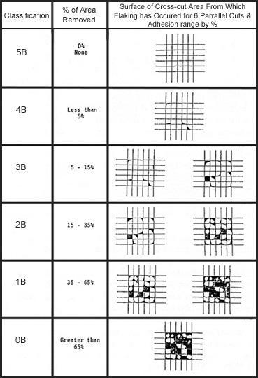
- The Paint Adhesion Test Kit, (P.A.T.) is a visual adhesion test produced by GARDCO, used for evaluating adhesion by cutting the paint or coating into small squares (cross-hatches), thereby reducing lateral bonding
- This kit contains tools and materials needed for conducting adhesion tests on paints and coatings, except for the blades (choose the one that fits your application best HERE)
- In accordance with ASTM Test Method D3359, method B and DIN Standard No. 53151.
- There are two kits available:
- The Cross Hatch Test Kit (12596) is great for any type of flat surface cross hatch adhesion test
- The Cross Hatch Radius Test Kit (14407) is ideal for curved surfaces, surfaces with a radius and pipes
- The ergonomic handle design gives comfortable and precision control in cross hatch testing and helps keep your hand in a natural position, preventing strain and fatigue
- Great for both right and left handed people
- ALL blades are sold separately so you can choose what works best for your application. Find them in the Accessories tab below or Click Here - options include:
- Blade cutters with 4, 5, 6, 11, 14 and 16 teeth
- Blade cutters for pipe radius
- Variable spaced blade cutters (Due to the accuracy of the spacings and the speed with which the test can be conducted, it is the preferred tool for use in this test except when evaluations must be made on coatings applied to surfaces which are neither flat or relatively smooth. Under these adverse conditions a single razor blade type cutter is often desirable under method A of ASTM.)
Technical Attributes
-
- Data
-
Paint Adhesion Kit Cutter Blades Part No. Certified Part No. Description Teeth Spacing Cross Hatch Segment Area Square 12599 15512 Variable Spaced 14 See Variable Spaced Page --- 12634 15509 API RP 5L2 Blade 16 1.6mm --- 12632 15510 Coarse Blade 4 2.4mm --- 12608 12609 Coarse Blade 11 2mm 4.00mm 12610 12611 Coarse Blade 6 2mm 4.00mm 12603 15505 Fine Blade 11 1mm 1.00mm 12600 12601 Fine Blade 6 1mm 1.00mm 12605 12606 Medium Blade 11 1.5mm 2.25mm 12633 15511 Thick Coatings Blade 5 5mm --- 12612 12613 Very Coarse Blade 6 3mm 9.00mm 14409 --- Pipe Radius Blade --- .75" Outer Diameter --- 14410 --- Pipe Radius Blade --- 1.98" Outer Diameter --- As general guide for coatings having a dry film thickness up to and including 2.0 mils (50 µm) space the cuts 1 mm apart and make eleven cuts (12603) unless otherwise agreed upon. For coatings having a dry film thickness between 2.0 mils (50 µm) and 5 mils (125 µm), space the cuts 2 mm apart and make six cuts (12610) unless otherwise agreed upon. For coatings having a thickness greater than 5 mils (125 µm) space the cuts 5.0 mm apart and make 5 cuts (12633) unless otherwise agreed upon.
Standards
Meets ASTM Test Method D3359, F1842; ISO 2409; Method B; DIN Standard No. 53151
Procedure
- Prepare test specimen as outlined in ASTM D3359.
- Position the blade in the handle with the holes facing the securing set screws, take care not to over tighten.
- Place the cutter assembly on the test specimen so that the guide and cutter rests on the substrate.
- Grasp handle and rotate it upward with respect to the line of contact of the guide with the test surface. During this motion, the tips of the cutter first contact the test surface when the top of the handle is about seven degrees with respect to the test surface. Continue this motion until the top surface of the handle is elevated to about 15 degrees. This is the correct attitude of the cutter assembly for the test.
- Apply enough pressure on the handle to insure that all of the cutter tips penetrate the test specimen supporting base, pull assembly along the test surface through 0.75 to 1 inch. Repeat this procedure with a second cut intersecting the first pattern at 90° (±5°). Evaluate results of the test as indicated in ASTM D3359, method B.
Tips: Before shipment, our blades must pass a cutter blade tooth accuracy inspection check. You can periodically check the accuracy of your cutter blade in the same manner. Use a small piece of polished plate glass. With a match or lighter, smoke a portion of the glass. This will leave an extremely black thin film. With the blade mounted in the handle, pull it across the film. All teeth should make tracks. If all teeth do not touch when used on a coated panel it will indicate that the panel surface is not plane or one or more of the teeth have been damaged.
Some customers using the cross-cut (or cross-hatch) adhesion blades have had problem getting all the teeth to cut evenly through their coating. From our experience, we have found that uneven cutting is usually due to warped panels. When using the crosscut blades, it is important that the panel being scratched be supported by a flat, rigid table or surface. Additionally, sufficient force must be used for the blades to cut completely through the coating. Often this is a catch-22 situation. If your panel is not supported sufficiently, then more applied pressure simply bends the panel.
Delivery Content
Paint Adhesion Test Kit for curved surfaces includes (2) 12614 blade holders/handles, hex wrench for changing blades, flaking brush, 5x LED hand held magnifier w/batteries (magnifier has 2 LED lights and 1.5" glass lens), Polyester Rope Fiber Laminate tape (12648), instruction guide, and a sturdy plastic carrying case with handle
All of the components are nested in die cut foam within the case. Blades sold separately - Click Here. Two blades Required: a curved blade for trans radius cut (14409 or 14410 - call for a custom size above .75") and a straight edge blade (12600) for the longitudinal cut.
Downloads
Accessories
Other Variations