Ford Cup Series History
The first known industry attempt to relate the results of various types of viscosity cups and to tie each to mathematical formulae based on fundamental measurements was by a sub-committee of ASTM Committee D-1 on Paint, Varnish, Lacquer and Related Products. The results of this work were published in the October 1950 ASTM Bulletin, No. 169.
The above referenced work included mathematical formulae which accommodated non-linearity at the lower range of each cup due to eddy current turbulence at the orifice. This permitted comparison of results between the 17 listed different types of cups above stated time minimums.
Also included in the above work were the results of an industry survey on the preference of viscosity measuring devices. Where the cup type instrument was applicable the preference was very heavily weighed in favor of the Ford Viscosity Cup series.
Based on the above work and on the stated preference for the Ford Viscosity cup series, an ASTM Standard Method of Test for Viscosity of Paints, Varnishes, and Lacquers by Ford Viscosity Cup was adopted in 1954 under ASTM Designation D 1200. There was minor revision to this method in 1958 with reapproval in 1965.
In D 1200-58 (1965) the dimensions of the cup and the orifice were shown. In place of the flow formulae that was developed in the earlier work a graph was included which related viscosity in stokes to efflux time in seconds for the Numbers 2, 3 and 4 Ford Viscosity Cups. The lines in the graph for cups Numbers 3 and 4 were in fairly close conformity to the earlier work except near the lower useable range. There is no comparison for the Number 2 cup as it was not included in the original work.
There was a change in the ASTM method in 1970, and it was published in following standards as D 1200-70 . The dimensions of the series were changed to metric, but there was no intended change to actual magnitude. The change with probably greatest impact was the reduction to quarter size the graph of “Standard Viscosity Curves for Ford Cups.” This was apparently done as for the first time there was included in the appendix to the method a flow formula for each of the three cups of the series.
It would appear that the flow formulae included in the appendix of D 1200-70 was intended to match the curves in the graph of D 1200-58 . In this attempt, however, there was even a greater divergence with respect to the work published in 1950. Of suspect is the format of the mathematical formula which is neither the same for each of the three cups of the series nor that developed in the earlier published work.
The majority of Ford #3 and #4 viscosity cups now in use are believed to closely conform to the definition for these cups as contained in the October 1950 ASTM Bulletin, No. 169. There are other cups, however, including the Ford #2 cup, that have been produced with the intent of complying either with ASTM Method D 1200-58 or ASTM Method D 1200-70. There should be no severe problem when comparing results from any of these different cups as long as such results are within specified efflux time limits. For results from these different cups to be theoretically within 5%, the efflux limits for the #2 cup should be within 40 to 100 seconds, the #3 cup between 22 and 120 seconds and the #4 cup between 25 and 100 seconds.
Background Information on Ford Viscosity Cups
As a service to its customers, The Paul N. Gardner Company is pleased to furnish the following background information on viscosity measurement and on the evolution of the Ford Viscosity cup as an important instrument for the measurement of this physical property.
A past study identified over 90 types of viscosity measuring devices. Nearly one third of these were of rotational type and another third were of the orifice capillary flow type. The remaining one third were about equally divided among bubble-ball-plate resistance devices, time-retention devices and miscellaneous mechanisms. This large number attests to the importance of this physical property and perhaps to the difficulty of its accurate determination.
The information that follows serves to assist the user of viscosity measuring equipment in the understanding of the various types and the influencing factors in the measurement.
General
All fluids possess a definite resistance to change of form and many solids show a gradual yielding to forces tending to change their form. This property, a sort of internal friction, is called viscosity. Classical physics defines the viscosity of a substance as the tangential force per unit area of either of two horizontal planes at unit distance apart, one of which is fixed, while the other moves at unit velocity, the space being filled with the substance. It is expressed in dyne seconds per square centimeter or poises. One poise equals 100 centipoises.
Rotational Instruments
From the above it is obvious why so many instruments are rotational type. Whether they are “bob in a cup”, “cone and plate” or any variation of these, their results, through a knowledge of surface area in contact with the substance being measured and the separation of these surfaces, reads in fundamental units—poises.
Rotational instruments are widely used in research and development laboratories. They are engineered for a wide range of viscosity values. The more elaborate devices provide values at different rates of shear for most any studies of the viscous properties of a substance. Auxiliaries may be accommodated such as automatic recorders.
There are disadvantages to the rotational instruments. Being complex instruments they are usually large and bulky. They may be delicate and require practiced technique for good results. They are costly. Probably one of the largest problems is in temperature control. At high rates of shear the substance being measured heats, and in order to retain a given temperature an elaborate temperature sensing and control system is required. The major influence of temperature will be covered later.
Orifice - Capillary Instruments
Consider first the capillary tube type instruments which are limited to measurements on relatively low viscosity substances. There are many different configurations. In simple form they consist of a reservoir with a capillary tube of known length and internal diameter connecting another reservoir at a lower level. The substance to be measured is filled into the upper reservoir, in exact amount, and the time for this amount to flow to the lower reservoir is determined. Another factor is now introduced — density of the substance. It is obvious that a material of high density should flow through the capillary tube faster than one of low density at the same viscosity.
Again we turn to classical physics which teaches that the volume of flow of a substance through a tube is directly proportional to time of flow, the pressure across the tube, the fourth power of the tube radius and inversely proportional to the length of the tube and the viscosity of the substance. Also, by definition, kinematic viscosity, the stoke, is the ratio of poise viscosity to density and the stoke equals 100 centistokes (stokes = poises ÷ density).
From the above definition it can be seen that the capillary tube type instruments also tie directly to fundamental units of measurements. If, however, gravity is the driving force creating the pressure drop across the tube, then density is a factor and the results are in stokes.
The capillary tube type instrument has served well as an accurate device for measurement in the lower part of the viscosity spectrum. But, again, there are limitations. They are fragile. They are limited to very low rates of shear. They are not easily adaptable to field use.
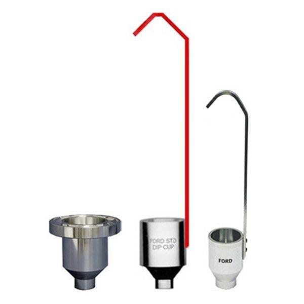
The orifice flow instruments known as viscosity cups can be looked on as an outgrowth of the capillary tube instruments. In these cups the length of the tube is much shorter and it is larger in diameter. They also normally accommodate a larger sample than the reservoir of the capillary tube. Even with these relative changes in dimension the relationships given above still hold except there is a deviation from linearity at the low end of each cup range, and the degree of deviation is more pronounced in those cups with the shorter effective length of tube. This is apparently due to the formation of eddy currents at higher rates of flow.
Since gravity is the driving force for the flow of a material from a viscosity cup and density is a factor, the measurement is in terms of kinematic viscosity or stokes.
There are numerous reasons why the viscosity cups are so widely used. They are surprisingly accurate. They are rugged and suitable for field use. They are relatively easy to clean. They are relatively low in cost.
The development of viscosity control cups has taken place in two main directions: One, toward precision type instruments for use in quality control laboratories and the other toward a simpler version for general use in the field. The biggest problem with the latter is they often lack standardization and tie back to fundamental units of measurements.
Other Types
A discussion of all of the other types of items making up the other third of the instruments surveyed is beyond the scope of this writing. It is suggested that further information can be found in publications such as the ASTM Manual 17- Paint & Coating Test Manual Gardner-Sward Handbook, 14th edition.
Liquid - Solid Mixtures
When particles of solid materials, such as pigments, are thoroughly mixed with liquids, the “interfacial friction” of the solid particles is additive to the “internal friction” of the liquid and is reflected in any viscosity measurement. Emulsions may behave in somewhat the same manner. Naturally, the higher the ratio of solid particles to the liquid the more pronounced and predominant will be the factor of “interfacial friction.”
Such liquid — solid mixtures introduce a very complex dimension to viscosity measurement. Some materials will not flow at all until a “force” exceeding a certain minimum is imposed. Some will reflect a lowering in viscosity as the rate of shear is increased. Some will reflect an increase in viscosity as the rate of shear is increased.
Evaluation of the flow properties of mixtures where the solid content is relatively high is best accomplished on rotational type equipment where the rate of shear is variable. However, a detailed discussion of such mixtures is beyond the scope of this writing.
Temperature
There probably is not enough emphasis on temperature in viscosity measurement with the simpler devices.
Temperature is an influencing factor in most all physical measurements. Within the range of room temperature, a soft iron bar will change in length by 0.00121% for each degree Celsius change in temperature. This small change can be neglected for most purposes. Consider though a volume of water under the same conditions and the change is over 20 times greater and must be considered in most accurate volume measurements such as the calibration of Weight per Gallon cups. The influence of temperature in viscosity measurements is much more severe. One group of refined mineral oils used for the calibration of viscosity measuring instruments changes in actual viscosity an average of more than 5% for each degree Celsius change in temperature in the range of 25 degrees Celsius. This is more than 200 times the influence of temperature on a volume of water and over 4000 times the influence on the length of a soft iron bar.
Generally, the change in viscosity as a function of temperature is also a function of viscosity — the higher the viscosity the greater the influence of temperature. The example given above for the calibrating oils is in the range of 50 to 500 centistokes and due to the nature of these materials they are less sensitive to temperature than most materials that will be considered for viscosity measurement.
Errors that are commonly made in temperature measurement and therefore in viscosity measurement involve one or more of the following: The thermometer may cover too wide a range and therefore is not sufficiently sensitive. The time lag of the thermometer is too great for the application. The “thermal well” effect of the thermometer is too great for the application. The sample is not thoroughly mixed and is not uniform throughout in temperature. There is temperature change during the measurement due to surfaces of equipment being at a temperature different from that of the sample.
Most materials change in viscosity as a function of temperature. Those normally measured with viscosity cups change in the range of 3% to 8% per degree Celsius change in temperature. Usually, the higher the viscosity the greater the change. For acceptable accuracy it is necessary to measure temperature at the same time that a viscosity cup reading is taken. When many determinations are to be made on similar products in the same viscosity range, it may be helpful to produce a graph for converting measured temperature and viscosity cup efflux seconds to seconds at a specified temperature, normally 25° Celsius.
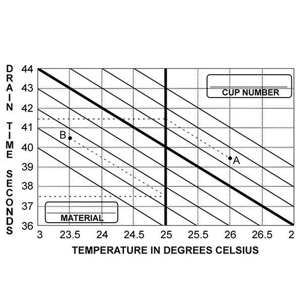
There are three variables to consider: viscosity, efflux time and temperature. All three can be shown on a graph with a family of curves as shown in the above example. Viscosity level is indicated by the diagonal lines, increasing from the lower left to the upper right. Such a graph can be prepared for a given material by taking readings with any of the Ford series cups over a limited temperature range as shown in the example. Within this limited range the plots of the obtained data will normally result in a straight line such as the wide diagonal line shown. Draw parallel lines as shown which represent different viscosity levels. Enter on the graph the material represented and the Ford cup designation with cup number.
Use the prepared graph by plotting measured temperature and efflux seconds. At "A" in the example these values are 26.0°C and 39.5 seconds. Read parallel to the diagonal lines to the intersection of the double vertical line which is 25.0°C, the target temperature. Reading horizontally to the left it is found that the corrected efflux seconds at 25°C is 41.5 seconds. Similarly, at "B" in the example, it is found that a reading taken at 23.5°C, when corrected to 25.0°C changes from 40.5 to 37.5 seconds.
Compensating for a measured temperature near to but not as specified must be done with caution. Even within the limited range of ±2.0°C the variation of viscosity with temperature may not be truly linear and any thinning materials used to adjust viscosity may also change the rate of this variation.
Gardco produced viscosity cups are calibrated with standard "G" Series oils. Centistoke viscosity of these oils is traceable to the National Institute of Standards and Technology. These oils are available from the Paul N. Gardner Company.
Shown in the above graph is the viscosity cup designation and the standard oil used for its calibration. Normally, cup calibration is at 25° Celsius, shown on the graph by bold lines intersecting with the curve in the circle. A set of these graphs for each cup in the series is included with all Ford Cups sold by Gardco.
Viscosity of most liquids, including the standard oils, are dependent on temperature. Efflux time in seconds for the indicated cup-oil combination from twenty (20) to twenty seven (27) degrees Celsius is shown in the above graph. The cup may be checked with this graph and the indicated oil with reasonable accuracy within these limits. For best accuracy, the standard oil label viscosity with temperature at 25°Celsius should be used. Conversion from viscosity in centistokes to efflux time in seconds is by the formula or table that defines the cup characteristics. Conversion between degrees Celsius and Fahrenheit below.
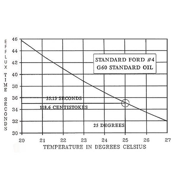
The applicable cup formula and table are furnished with each viscosity cup sold as an additional customer service by the Paul N. Gardner Company or by licensed distributors.
| Temperature Scale Conversion Between Celsius & Fahrenheit | ||||
| Degrees | Degrees | |||
| Celsius | Fahrenheit | Celsius | Fahrenheit | |
| 20.0 | 68.0 | 23.6 | 74.5 | |
| 20.1 | 68.2 | 23.7 | 74.7 | |
| 20.2 | 68.4 | 23.8 | 74.8 | |
| 20.3 | 68.5 | 23.9 | 75.0 | |
| 20.4 | 68.7 | 24.0 | 75.2 | |
| 20.5 | 68.9 | 24.1 | 75.4 | |
| 20.6 | 69.1 | 24.2 | 75.6 | |
| 20.7 | 69.3 | 24.3 | 75.7 | |
| 20.8 | 69.4 | 24.4 | 75.9 | |
| 20.9 | 69.6 | 24.5 | 76.1 | |
| 21.0 | 69.8 | 24.6 | 76.3 | |
| 21.1 | 70.0 | 24.7 | 76.5 | |
| 21.2 | 70.2 | 24.8 | 76.6 | |
| 21.3 | 70.3 | 24.9 | 76.8 | |
| 21.4 | 70.5 | 25.0 | 77.0 | |
| 21.5 | 70.7 | 25.1 | 77.2 | |
| 21.6 | 70.9 | 25.2 | 77.4 | |
| 21.7 | 71.1 | 25.3 | 77.5 | |
| 21.8 | 71.2 | 25.4 | 77.7 | |
| 21.9 | 71.4 | 25.5 | 77.9 | |
| 22.0 | 71.6 | 25.6 | 78.1 | |
| 22.1 | 71.8 | 25.7 | 78.3 | |
| 22.2 | 72.0 | 25.8 | 78.4 | |
| 22.3 | 72.1 | 25.9 | 78.6 | |
| 22.4 | 72.3 | 26.0 | 78.8 | |
| 22.5 | 72.5 | 26.1 | 79.0 | |
| 22.6 | 72.7 | 26.2 | 79.2 | |
| 22.7 | 72.9 | 26.3 | 79.3 | |
| 22.8 | 73.0 | 26.4 | 79.5 | |
| 22.9 | 73.2 | 26.5 | 79.7 | |
| 23.0 | 73.4 | 26.6 | 79.9 | |
| 23.1 | 73.6 | 26.7 | 80.1 | |
| 23.2 | 73.8 | 26.8 | 80.2 | |
| 23.3 | 73.9 | 26.9 | 80.4 | |
| 23.4 | 74.1 | 27.0 | 80.6 | |
| 23.5 | 74.3 | |||
| F°=(C° x 1.8)+32 C°=(F°- 32)÷1.8 | ||||
Care of Cup
The GARDCO viscosity cups are precision instruments. To retain them in their initial condition and calibration they should be cleaned following each use with a suitable solvent and a soft brush or lint-free cloth. Particular care should be used in cleaning the orifice to avoid leaving deposits or scratches on the internal surfaces. It is good practice to retain one or more standard oils which can be used to periodically insure that each cup retains its initial calibration. Such oils are available from Gardco. The “seconds” values in the following table are approximate and should be recalculated from the formula given earlier and with the exact centistoke value given on the label of standard oil.
| Approximate Efflux Seconds From Standard Ford Cups | ||
| Cup No. | Standard Oil | Efflux Seconds |
| 0 | G6 | 93 |
| 1 | G10 | 84 |
| 2 | G35 | 64 |
| 3 | G60 | 56 |
| 4 | G60 | 35 |
| 5 | G200 | 39 |
| Divide Values By 2 For Dip Cups | ||
To find the exact efflux seconds, substitute the centistoke value of the oil from the bottle label in the conversion formula sheet furnished with the cup and solve the formula or find the label centistoke value in the body of the conversion table and read from the table the applicable efflux seconds.
CAUTION: Silicone fluids should not be used to calibrate viscosity cups. These materials change the interface between the cup surface and the test material and therefore change the cup calibration. The following is taken from ASTM D 445: "Viscometers used for silicone fluids should be reserved for the exclusive use of such fluids. Solvent washings from these viscometers should not be used for cleaning other viscometers."
Certification
Any particular Gardco Standard or Dip Cup - orifice combination will be certified, as an extra cost service, to within 0.1 seconds and .01 degrees Centigrade on a standard oil selected for the combination midrange. Both the viscosity of the oil and the temperature measuring devices are traceable to National Institute of Standards and Technology. This certification complies to the requirements of ANSI/NCSL Z540-1 as applicable. Such certification is voided by the interchange or replacement of the cup orifice.
The information contained herein, or supplied by us on our behalf in any other manner, is based on data obtained by our own research and is considered accurate. However, NO WARRANTY IS EXPRESSED OR IMPLIED REGARDING THE ACCURACY OF THESE DATA, THE RESULTS TO BE OBTAINED FROM THE USE THEREOF, OR THAT ANY SUCH USE WILL NOT INFRINGE ANY PATENT. This information is furnished upon the condition that the person receiving it shall make his own tests to determine the suitability thereof for his particular purpose.
Auxiliaries
A suitable timer is a stopwatch which has a seven-jewel movement and indicates to 1/5 second. A convenient stopwatch stand, Catalog No. is available to facilitate use of this timer. Another suitable timing device is a digital electronic timer, Catalog No. which has a range of 10 hours and indicates to 1/100 second timing interval.
A convenient auxiliary is a square glass plate which when placed on a filled cup will prevent flow from the orifice. It can also be used to assist in removing material from a cup that has been overfilled. Cemented to this glass plate is a circular level to be used when leveling the cup support.
The thermometer used should be readable to the nearest 0.1 degrees Celsius. The glass thermometer recommended by Gardco is so scaled. It is 4.5 inches long and has a range from 20 to 30 degrees C. See following pages for other expanded scale glass thermometers.
A 250ml stainless steel beaker is a convenient receiver for the efflux stream of the Gardco Standard Ford Cup. Being metal, it conducts heat rapidly for any temperature adjusting of the sample that may be necessary. It is also of adequate size to accept the body of the cup for draining or cleaning.
Tripod Support
In order to provide the best possible support for not only the new Gardco Standard Ford Viscosity Cups but also for other cups of the same type a special tripod support has been designed. A drawing of this support is shown above right. It is constructed of aluminum. The legs of the tripod are adjustable in length so that the viscosity cup can be accurately leveled for best possible results. The spread of the tripod legs is adequate to provide good stability and make accidental spilling of the cup contents most difficult .
Glass Thermometers For Viscosity Measurement by Efflux Cups
A viscosity measurement is no more accurate or meaningful than the associated temperature measurement.
Temperature is one of the parameters of viscosity, just as the height of a rectangle as well as the width must be known for proper definition. Most all liquids change in viscosity as temperature changes. Normally the rate of change is greater at higher viscosity levels and the rate of change is not linear. Even the standard oils that are used for the calibration of viscosity cups change in viscosity in the range of 3% to 8% per degree Celsius at the normal use temperature of 25°C.
Glass thermometers are preferred at least as reference temperature measuring devices for viscosity measurement as they are more likely to be unusable if damaged or out of calibration. Suitable glass thermometers which have been standardized and listed in ASTM methods are detailed in this leaflet.
Unless a glass thermometer, with continuous mercury column, readable to the nearest tenth degree celsius or equivalent, is used in viscosity determination, the final readings are open to questioning. If a metallic dial thermometer is being used it could have been dropped or otherwise damaged causing a false reading. If a thermocouple device is being used it may be out of calibration. Even if a glass thermometer is used but it can only be read to the nearest degree, results may be misleading. It is therefore good practice to retain a glass thermometer, readable at least to the nearest tenth degree celsius or equivalent and periodically check all other temperature measuring devices in constant service with this “standby” thermometer. Such practice insures that accurate temperature measuring capability is maintained.
Glass thermometers having the characteristics of either ASTM 17C or 17F have been found to be adequate for direct use or as a reference instrument in association with efflux cup viscosity measurement. For laboratory use the even further expanded scale ASTM specified 45C or 45F may be preferred. The specifications of each of these thermometers is given in the following tables:
| Technical Data | ||||
| ASTM Number | 17C | 17F | 45C | 45F |
| ASTM Name: | Saybolt Viscometer | Saybolt Viscometer | Kinematic Viscosity | Kinematic Viscosity |
| Range: | 19 to 27C | 66 to 80F | 23.6 to 26.4C | 74.5 to 79.5F |
| For Test At: | 25C | 77F | 25C | 77F |
| Immersion | Total | Total | Total | Total |
| Graduations | ||||
| Subdivisions | 0.1C | 0.2F | 0.05C | 0.1F |
| Long Lines at Each: | 0.5C | 1F | 0.5F | |
| Number at Each: | 1C | 2F | 1F | |
| Max. Scale Error: | 0.1C | 0.2F | 0.2F | |
| Inscription: | ASTM 17C | ASTM 17F | ASTM 45C | ASTM 45F |
| Heating Limit: | 100C | 212F | 104C | 220F |
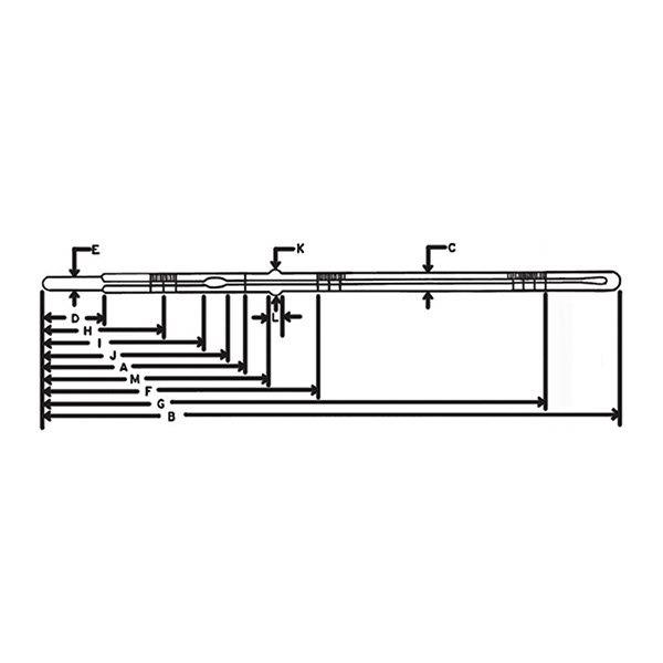
| Total Length (B): | 275/10.8* | 275/10.8* | 305/12.0* | 305/12.0* |
| Stem O.D. (C): | 6.5/0.26* | 6.5/0.26* | 7.2/0.28* | 7.2/0.28* |
| Bulb length (D): | 30/1.18* | 30/1.18* | 50/1.97* | 50/1.97* |
| Bulb O.D. (E): | 5/0.20* | 5/0.20* | 6.5/0.26* | 6.5/0.26* |
| Min. Scale Ht. (F): | 143/5.63* | 143/5.63* | 142/5.59* | 142/5.59* |
| Max. Scale Ht. (G): | 227/8.94* | 227/8.94* | 205/8.07* | 205/8.07* |
| Ice Point Range: | NA | NA | 31.5 to 32.5F | |
| I.P. Scale Ht. (H): | NA | NA | 82/3.23* | 82/3.23* |
| Min. Chamber Ht. (I): | NA | NA | 100/3.94* | 100/3.94* |
| Max. Chamber Ht. (J): | 60/2.36* | 60/2.36* | 125/4.92* | 125/4.92* |
| Ring O.D. (K): | 9/0.35* | 9/0.35* | NA | NA |
| Ring Length (L): | 5.5/0.22* | 5.5/0.22* | NA | NA |
| Ring Ht. (M): | 114/4.49* | 114/4.49* | NA | NA |
| * Millimeters/Inches — Values are average. NA Not Applicable. |
||||