Fisher Viscosity Cups
Article No. 13691
Gardco Fisher Dip Viscosity Cup #1
The Fisher Cups have all the advantages associated with a precision laboratory cup. There are both Standard and Dip Cup versions available and they have removable orifices that are interchangeable.
Download Excel Viscosity Chart HERE
Certificate:
Features
- Designed with a “snap in, snap out” type orifice, that permits coverage of the complete viscosity range with one cup and can be replaced if damaged rather than requiring replacement of the entire cup.
- Conversion formulas and table relating efflux time in seconds, to the nearest tenth of a second, to viscosity in centistokes are furnished with each Gardco/Fisher viscosity cup.
- Gardco/Fisher cups are not matched by any other such cups, either with respect to the advantages listed above, in highest quality of workmanship and in continuing quality control procedures.
- Qualifies for certification under ANSI/NCSL Z540 or ISO/IEC 17025, ISO 9001 as applicable. Conforms to ISO 9000 when ordered with calibration certification.
- Calibration of the new Gardco/Fisher cup is traceable to the National Institute of Standards and Technology.
- Gardco/Fisher cups are machined from solid bar stainless steel with brass, readily removable orifices. The support rods are stainless steel.
- The stainless steel support rods are offset from the side of the cup and secured to the cup sidewall below the cup rim. This eliminates errors due to test material drainage from support surfaces.
- Separation of the support rods from the cup by 18% and securing the rods to the cup below the cup rim provides best possible conditions for cleaning.
- Gardco/Fisher calibrated viscosity cups are designed, manufactured, calibrated and sold only by the Paul N. Gardner Company.
The Fisher series of viscosity cups as originally designed and produced, provided some advantages over other existing dip viscosity cups. They accommodated a larger sample of the test material. The orifice was considerably longer than its diameter resulting in cup efflux time more closely proportional to viscosity. However, there were deficiencies in the design. The cup was difficult to clean. It was costly to produce and to calibrate. A damaged or enlarged orifice resulted in necessity for replacement of the entire cup.
The Gardco/Fisher viscosity cups retain the original internal cup dimensions and the same orifice length and diameter but with the following improvements: The weight of the new cup has been reduced to 44% of the weight of the original cup for easier temperature control when cup and material are not at the same temperature. The orifices are of the readily replaceable type permitting coverage of the complete viscosity range with one cup and interchangeable orifices. The orifice may be readily replaced if damaged rather than requiring replacement of the entire cup. The design of the lower portion of the cup eliminates hard to clean areas. The design directs the flow of all test material from the outside of the cup away from the efflux stream improving cup accuracy. Rod supports are designed and secured to the cup in a manner to prevent drainage to the inside of the cup and to provide easier cleaning. In addition to physical improvements, the cups are furnished with conversion formulas and a table which relates the nearest tenth of a second of total efflux time to viscosity in centistokes. This table is particularly useful in determining efflux time in seconds when viscosity in centistokes is known.
The Gardco/Fisher viscosity cups are calibrated at time of manufacture to within 2% of target efflux time. This calibration is with standard oils traceable to the National Institute of Standards and Technology. At an additional cost any cup/orifice combination is available with a CERTIFICATE OF CALIBRATION. The procedures and conditions of calibration on which the certificate is based qualify under ANSI/NCSL Z540 or ISO/IEC 17025, ISO 9001, as applicable, & conforms to ISO 9000 when ordered with certification.
The Gardco/Fisher cups are produced to very close mechanical tolerance in elaborate jigs and fixtures. Such equipment not only insures that each cup is correctly produced but also that all cups are identical. All parts of the cup are of stainless steel except for the orifice and the name plate.
Technical Attributes
-
- Cup Model
- Fisher Dip Cup
-
- Cup No.
- 1
-
- Data
-
Orifice No. Seconds Range Centistoke Range Midrange Sensitivity¹ Calibration Oil No./Centistokes² 1 22 - 60 11 - 48 0.9 G 20 / 35 2 14 - 60 19 - 136 2.5 G 35 / 68 3 10 - 60 35 - 320 10.3 G 60 / 117 4 10 - 60 167 - 1125 19.0 G 200 / 468 ¹ Centistoke Values are Nominal - Actual Values Printed on Bottle Labels.
² Stated as Centistokes per Second of Efflux Time.
More Information
Fisher Dip Cup Construction
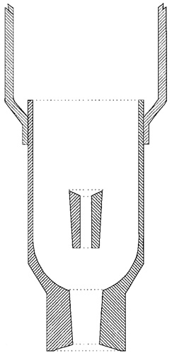
The body of the cup is machined from solid bar stock stainless steel. Note the conical opening for the orifice which permits gentle “tapping in” or “tapping out” of the orifice. Also note that the cup shape ensures that materials draining from the exterior of the cup flow away from the orifice.
Stainless steel rods supporting the cup are formed so that they are held a distance away from the cup. The pad formed at the end of the support rod is welded to the cup below the cup rim. This design prevents any test material from the rod flowing to the inside of the cup. The increased separation of the two support rods also makes it easier to clean the cup.
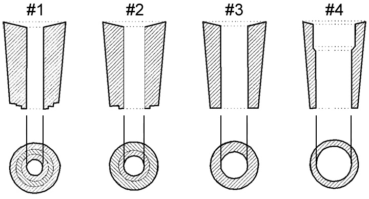
The orifices for the cup are machined from brass with the exact conical exterior to match the opening in the base of the cup. Positive orifice identification is assisted by “steps” at the base of the orifice.

Image #1 has a double shoulder.
Image #2 has a single shoulder.
Image #3 has no Shoulder.
Image #4 has no Shoulder.

Procedure
It is helpful and results will be more consistent if all viscosity determinations are made in a room that is free from drafts or quick temperature change and is within ±3° C ( ±5° F ) of the viscosity measuring temperature of 25° C.
Fisher Dip Cup Instructions
- Select the proper cup/orifice combination to be used from the Specification Table (Fig. 1), which is dependent on the expected viscosity range of the material to be measured.
- Insure that the cup is clean and that there is no residual dried material in or around the orifice.
- Adjust the temperature, if necessary, of the test material.
- Completely immerse the cup into the material to be measured in a location free from bubbles or foam, holding the cup vertically.
- Measure and record the temperature of the material that is encompassed by the cup.
- Hold cup vertically by inserting index finger into handle ring. In a quick, steady motion, lift the cup out of the sample material, starting the timer when the top edge of the cup breaks the surface. During the flow time, hold the cup no more than 6” above the level of the sample material.
- Stop the timer when the first definite break in the stream at the base of the cup is observed.
- Record the number of seconds of efflux time, temperature and the cup number. As an option to the preceding step, refer to the Insta Visc viscosity calculator Insta Visc App or conversion table for the cup to determine the centistoke viscosity for the measured efflux time in seconds and record this value and the measured temperature. (Example: Gardco/Fisher Cup #2, 35.0 seconds at 25.1°C.)
- Promptly clean the cup unless it will be used immediately for a rerun of the same material.
Fisher Standard Cup Instructions
- Adjust the sample to measuring temperature, usually 25°C (77°F)
- Select the cup that will provide readings which are well within the cup range.
- Make sure that the cup is clean and place it in its support.
- Make sure that the cup is level.
- Place a finger under the cup orifice and fill the cup with bubble free test material. The cup is full when the meniscus disappears where the liquid joins the sidewall of the cup. If the cup is over-filled, scrape the excess into the cup well with a spatula or by passing the cover plate across the top of the cup. Note: that the finger can be removed from the orifice when the cover plate is in place.
- Start a timer as the cover plate is removed from the cup.
- Determine the temperature of the efflux stream. If there is a significant change during the test it should be repeated.
- Stop the timer at the first break in the efflux stream, one or two inches below the orifice.
- Record the cup type and number, measured temperature and efflux time. As an option to the preceding step, refer to the Insta Visc viscosity calculator Insta Visc App or conversion table for the cup to determine the centistoke viscosity for the measured efflux time in seconds and record this value and the measured temperature. For best accuracy, average three or more readings.
- Promptly clean the cup giving special care to the orifice.
Accessories
Other Variations

